
What is milling chatter?
One issue that machinists face when milling is chatter. Chatter occurs when the tool, toolholder, and spindle vibrate at the resonant frequency of the assembly. It generates a loud, dissonant noise. The vibration of the assembly leaving visible waves on the surface of the part. Consequently, this vibration leads to a varied cutting edge for the next pass. The varied edge exacerbates the vibration that the assembly is already experiencing. Thus, chatter can interfere with the accuracy of the operation, cause poor surface finishes, and shorten tool or machine life.
What can be done?
There are a few tips to decreasing chatter while milling or using a lathe. Increasing rigidity of the assembly can minimize vibration overall. This can be accomplished by shortening the tool. When milling at high spindle speeds, there may be stable zones without problem-causing vibration. A Stability Lobe Diagram can help determine the appropriate chip width and spindle rpm. The unstable region denotes chatter, while the stable region denotes optimal chip width and spindle speed. Typically, machine operators reduce RPM’s when they encounter chatter issues causing longer run cycles. Understanding the stability lobe diagram allows exploration of higher RPM’s as well.
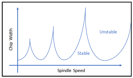
Stability Lobe Diagram
Latest Posts
- Inside Axis Fab’s New Manufacturing Facility: Built to Better Serve Customers
- Why Should I Work with a Full Service Shop? And Other FAQs We Hear at Axis Fab
- Why Customers Choose Axis Fab as Their Manufacturing Partner
- Building Better Customer Outcomes Through Strong Company Culture
- Case Study: How a True Manufacturing Partner Can Reduce Costs